1. Product Category Identification
The ABB FPX86-9329-C is a printed circuit board (PCB) subassembly belonging to ABB's legacy drive and control product lines, specifically the FPX86 series of interface and signal conditioning boards. This series was primarily used in ABB's DC drive platforms (such as the DCS400, DCS500, and early ACS AC drives) from the mid-1980s through the late 1990s. The "-C" suffix indicates the third revision of the board, incorporating design improvements for enhanced noise immunity and component availability.
Unlike standard commercial products, the FPX86-9329-C is:
-
A factory-original spare part – not a general-purpose board for new designs
-
Typically programmed or calibrated for a specific drive model and firmware version
-
Not user-repairable at component level (multi-layer PCB with proprietary ASICs)
2. Product Overview
The ABB FPX86-9329-C functions as an interface board between the drive's main control logic and the power electronics section. It typically performs signal conditioning, isolation, and protection functions, including:
-
Gate drive signal distribution – routing firing pulses from the control board to the IGBT or thyristor gate drivers
-
Current and voltage feedback scaling – converting analog signals from current transformers (CTs) and voltage dividers to levels readable by the drive's ADC
-
Temperature monitoring – interfacing with thermistors or RTDs on heatsinks and power modules
-
Fault detection – Desaturation (desat) protection, overcurrent latch, and ground fault detection circuits
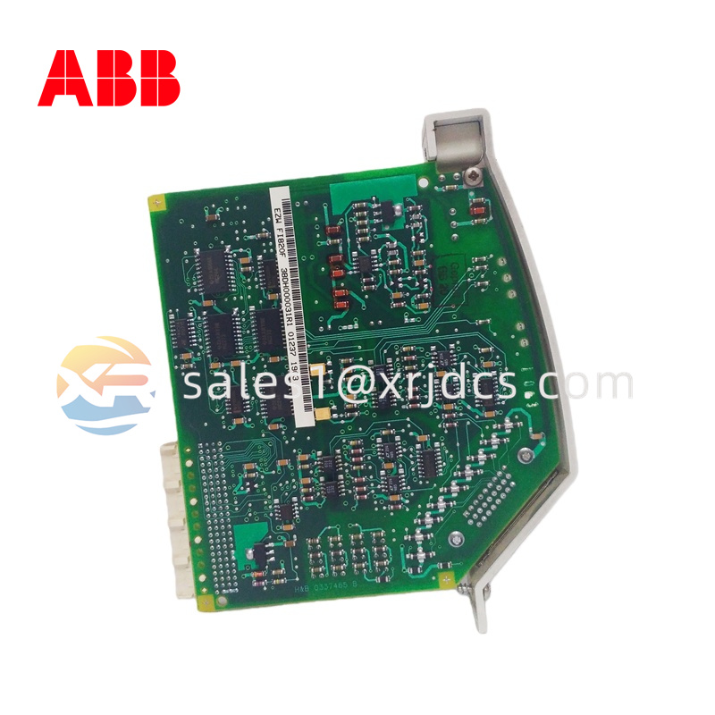
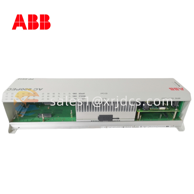
The board is designed for installation inside the drive's control compartment, typically mounted on standoffs above the main control board (NINT, NDCU, or similar) or near the power terminal block. It is not a standalone device – it has no user interface, no display, and no external controls.
3. Technical Specifications
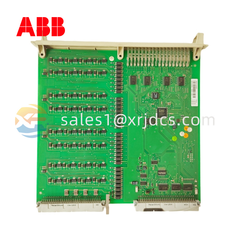
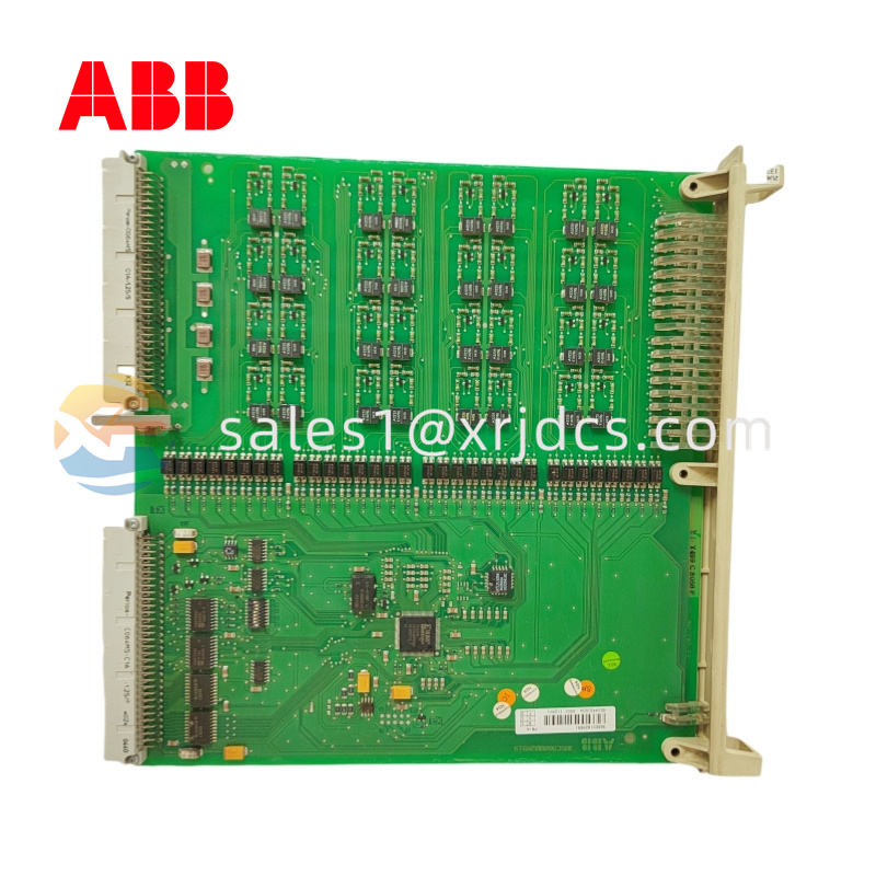
Physical Characteristics:
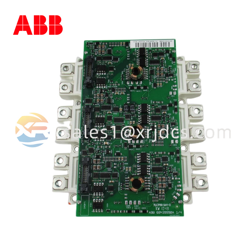
The FPX86-9329-C measures approximately 220mm in length, 120mm in width, and 1.6mm in thickness – a standard Eurocard 3U format but with non-standard mounting holes. The board is a six-layer FR4 PCB with plated-through holes, immersion tin finish (not HASL), and gold-plated edge fingers on the P1 connector (64-pin DIN 41612). Board weight is approximately 0.25 kg (0.55 lb).
Power Requirements:
The board draws its operating power from the backplane or drive control board via the P1 connector. Typical consumption is 5V DC at 250mA, plus ±15V DC at 50mA for analog circuitry. Total power dissipation is less than 2.5W – no forced air cooling required beyond the drive's internal fan. Reverse polarity protection is implemented via a series Schottky diode (D1, 1N5819).
Signal Interface:
-
Analog inputs: 4 differential channels, ±10V or 4–20 mA (jumper selectable per channel). Input impedance: 100kΩ (voltage) or 250Ω (current). 12-bit resolution (0.025% of scale).
-
Analog outputs: 2 channels, 0–10V or 0–20 mA. Output impedance: 10Ω (voltage) or open collector (current). Update rate: 1 kHz.
-
Digital inputs: 8 optically isolated, 24V DC nominal (range 10–30V). Response time <1 ms.
-
Digital outputs: 4 relay outputs (Form-A, 2A at 30V DC / 0.5A at 125V AC) plus 2 open-collector transistor outputs (50mA, 30V max).
-
Gate drive outputs: 6 channels (for 3-phase IGBTs), +15V / -8V pulse, 5A peak, isolated to 2500Vrms.
Environmental Limits:
-
Operating temperature: 0°C to +55°C (32°F to 131°F) – derate to 45°C at full analog accuracy
-
Storage temperature: –40°C to +85°C (–40°F to +185°F)
-
Humidity: 5–95% non-condensing
-
Vibration: 1g @ 10–150 Hz (IEC 60068-2-6)
-
Altitude: Up to 2000 meters (6560 feet) without derating
4. Safety & Certifications (Early Section)
The FPX86-9329-C was designed to meet international safety standards for industrial drive equipment. When installed inside an ABB drive enclosure, the combined assembly carries the following approvals:
| Certification |
Standard |
Status |
| CE |
EN 61800-3 (EMC), EN 61800-5-1 (Safety) |
Compliant (original drive) |
| UL / cUL |
UL 508C (Power Conversion Equipment) |
Recognized component |
| CSA |
C22.2 No. 274 (Adjustable Speed Drives) |
Recognized component |
| RoHS |
2011/65/EU |
Not compliant (manufactured before 2006) |
Safety Features Built Into the Board:
-
Galvanic isolation: 2500Vrms between logic side (P1 connector) and power side (gate drives and analog inputs)
-
Creepage and clearance: Minimum 8mm at 600V working voltage (pollution degree 2)
-
Overvoltage protection: MOVs on all analog inputs (clamp at 30V)
-
Fault latching: Desaturation detection shuts down gate drives within 2µs of detecting IGBT short-circuit
-
Soft-start power supply: Limits inrush current to the board's onboard DC-DC converters
5. Functional Description
Understanding the FPX86-9329-C's role in the drive system requires a brief overview of a typical ABB drive architecture:
Signal Flow (Input Side):
-
Current feedback from the drive's output phase current transformers (CTs) enters the board via connector X3. The signals are typically 0–5V AC, representing 0–200% of rated current.
-
Voltage feedback from the DC bus or output phases enters via X4. A resistive divider reduces the 700V DC bus to 0–10V.
-
Temperature sensors (PTC thermistors) on the heatsink connect to X5. The board's comparator circuit generates a "heatsink overtemp" digital signal when resistance exceeds 4kΩ.
-
External digital inputs (start/stop, enable, reset) from the drive's terminal block route through X6 and are optoisolated before being passed to the main control board.
Processing on the Board:
-
The analog signals are filtered (2-pole low-pass, cutoff 1 kHz) and scaled by precision resistor networks (0.1% tolerance).
-
Scaled signals feed a 12-bit ADC (AD7874 or equivalent) – four channels simultaneously sampled for accurate current measurement.
-
The ADC communicates with the main control board via an SPI bus over the P1 connector.
-
Digital inputs are latched in a shift register (74HC165) and read by the control board every 250µs.
Signal Flow (Output Side – Gate Drives):
-
The main control board sends six PWM gate signals (for IGBTs U+, U-, V+, V-, W+, W-) to the FPX86-9329-C via the P1 connector.
-
Onboard gate drive optocouplers (HCPL-316J or similar) provide 2500V isolation and desaturation detection.
-
The optocoupler outputs drive a totem-pole transistor pair (2N4401/2N4403) that supplies ±15V, 5A peak to the IGBT gate.
-
If a desaturation fault occurs, the optocoupler pulls the "fault" line low, which the main control board reads and uses to trip the drive and display a "short circuit" fault.
Protection Circuits:
-
Overcurrent latch: Independent analog comparator (LM339) monitors the CT signals. If current exceeds 250% of drive rating for >10µs, the comparator triggers a hardware latch that immediately blocks gate drives – this happens faster than the control board can respond.
-
DC bus overvoltage: A window comparator checks the scaled DC bus voltage. If bus exceeds 820V DC (for 480V drives), the gate drives are blocked and the brake chopper is turned on.
6. Installation & Replacement Procedure
Before You Begin: The FPX86-9329-C must be installed by a qualified electrician or drive technician. Capacitors inside the drive can store lethal voltage for minutes after power removal.
Removal of Old Board:
-
De-energize the drive – open the upstream disconnect and lockout/tagout.
-
Wait 10 minutes for DC bus capacitors to discharge. Measure voltage between DC bus terminals (U+ and U-) – must be <50V DC before proceeding.
-
Open the drive enclosure – typically four Phillips screws on the front cover.
-
Locate the FPX86 board – usually mounted vertically near the power terminal block or horizontally above the main control board.
-
Disconnect all ribbon cables – note their orientation and connector positions. Use a flathead screwdriver to gently release locking tabs; do not pull on the wires.
-
Remove mounting screws – typically four M3 standoff screws (torque 0.8 Nm). Keep the screws and insulating washers.
-
Lift the board out – if the board has edge connectors, rock it gently to unseat. Do not bend the board.
Installation of New/Replacement Board:
-
Compare the new board to the old one – verify the "-C" revision matches. Check that all connectors are in the same locations.
-
Transfer any jumpers or DIP switch settings from the old board to the new board. The FPX86-9329-C typically has:
-
S1 (4-position DIP): Sets analog input range (0–10V or 4–20mA per channel)
-
J1-J4 (jumpers): Enable/disable termination resistors for RS-485 (if present)
-
VR1 (trimpot): Factory calibration only – do not adjust
-
Install the new board using the original standoffs and screws. Torque to 0.8 Nm.
-
Reconnect all ribbon cables – ensure connectors are fully seated (you should hear a click).
-
Close the drive enclosure and secure the cover.
-
Apply power and monitor the drive's keypad display for fault codes. If the drive shows a "board mismatch" or "ID run required" fault, perform a drive parameter backup and restore (see Section 9).
Post-Installation Verification:
-
Verify that the drive reads correct current and voltage values (compare with a clamp meter).
-
Run the motor at low speed (5–10%) and listen for normal operation.
-
Check for any fault codes – common post-replacement faults include:
-
Fault 1 (Overcurrent): Indicates incorrect current transformer wiring or board configuration
-
Fault 4 (Board ID mismatch): Requires firmware update or parameter restoration
-
Fault 7 (Analog input out of range): Check jumper settings on S1
8. Storage & Shelf Life
Because the FPX86-9329-C is an obsolete spare part, you may need to store it for years before use. Proper storage extends its useful life:
Storage Conditions:
| Parameter |
Requirement |
| Temperature |
15°C to 35°C (59°F to 95°F) – avoid extremes |
| Humidity |
30–60% non-condensing |
| Atmosphere |
No corrosive gases (H2S, SO2, Cl2) – avoid battery rooms, chemical storage |
| Packaging |
Original anti-static bag (or equivalent) – do not store on conductive foam |
| Orientation |
Flat (horizontal) – prevents warping |
| Shelf life (unpowered) |
10 years (limited by electrolytic capacitor degradation) |
Before placing a stored board into service:
-
Visually inspect for corrosion or capacitor bulging.
-
Reform electrolytic capacitors – if board has been stored >3 years, apply low voltage (5V DC) through a 1kΩ current-limiting resistor for 24 hours before installing. This rebuilds the capacitor's oxide layer.
-
Check the battery (if present) – replace if voltage <2.8V.
-
Inspect edge connectors – clean with isopropyl alcohol and a soft brush if dull or tarnished.
7. Firmware & Configuration Notes
The FPX86-9329-C contains no onboard firmware (no EPROM or flash). It is a "dumb" interface board – all intelligence resides on the drive's main control board (NINT, NDCU, or RDCU). However, certain hardware configurations must match the drive's software expectations:
Configurable Elements:
| Component |
Function |
Default Setting (-C revision) |
| S1-1 |
Channel 1 analog input range |
OFF = 0–10V (ON = 4–20mA) |
| S1-2 |
Channel 2 analog input range |
OFF = 0–10V |
| S1-3 |
Channel 3 analog input range |
OFF = 0–10V |
| S1-4 |
Channel 4 analog input range |
OFF = 0–10V |
| J1 |
CT scaling factor |
OPEN = 1000:1 CT ratio (CLOSED = 2000:1) |
| J2 |
Bus voltage divider enable |
CLOSED = enabled (standard) |
| VR1 |
ADC reference voltage trim |
Factory set to 2.500V ±0.01V – do not adjust |
After replacing the FPX86 board, you may need to:
-
Restore drive parameters – If the drive has lost its configuration, reload from a saved backup (.PRM file from DriveWindow or similar).
-
Perform an "ID Run" (motor identification) – Required if the drive's current scaling has changed. Navigate to Parameter Group 99 (Start-up Data) and set "99.10 ID Run" to "ON".
-
Calibrate analog inputs – Use the drive's "Analog Input Calibration" routine (typically under Parameter Group 13). This corrects for component tolerances.
8. Application Fields
The FPX86-9329-C is not a standalone product – it exists only as a spare part for specific ABB drives. Applications where these drives are still in service include:
-
Metal processing – strip tension control in rolling mills (DC drives)
-
Paper and pulp – winder and unwinder drives (DC and early AC drives)
-
Crane and hoist systems – DC drives for bridge and trolley motions
-
Elevators (modernization projects with original DC drives)
-
Mining conveyors – long-distance belt drives with ACS 600/800
-
Marine propulsion – bow thrusters and azimuth drives (older vessels)


 Switzerland